The Facility
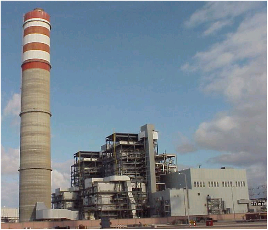
The Sidi Krir Unit 3 & 4 Power Plant, developed by InterGen and Edison SpA, is located about 30 kilometers west of Alexandria, Egypt. It is a natural gas fired power plant and at 685 MW generating capacity, is the largest IPP thermal power plant in the Middle East.The plant consists of two power blocks, which share a common membrane based Seawater Desalination system for their make-up water requirements. The desalination system gets the water from the Mediterranean Sea.
Project Overview
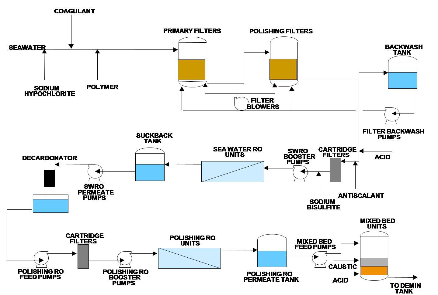
The seawater is chlorinated by a hypochlorite feed system. Since feed from a deep-water source is relatively low in suspended solids, BOD and Oil & Grease, the pretreatment system consists of two stage contact filtration with coagulant and polymer dosing upstream of the filtration system. The filtration system consists of a primary & polishing filter battery of 4 x 33% units.The filtered water is then processed through seawater reverse osmosis units operating in 3 x 50% configuration. The reverse osmosis booster pumps are provided with Energy Recovery Turbines as a means of energy recovery to optimize energy consumption.

Scope of Service
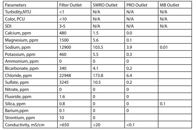
The raw seawater TDS is around 43,000 ppm and the seawater reverse osmosis unit is designed to produce permeate having less than 350 ppm TDS at 36% recovery. A part of the seawater reverse osmosis permeate is used for potable and fire water use and the remainder is stored in a service water tank for further polishing.The polishing system consist of 3 x 50% reverse osmosis trains operating at 85% recovery producing a permeate of less than 10 ppm TDS. The reject from the polishing reverse osmosis trains is recycled back to the upstream of seawater reverse osmosis cartridge filters to improve the overall recovery of the system. Permeate from these reverse osmosis trains is further polished using 3 x 50% mixed bed polishers. The Mixed Bed polishers produce demineralized quality water with less than 0.1 mS/cm conductivity and are stored in the demineralized water tank.
Design Water Analysis

Process Flow Diagram


