The Facility
HMEL (HPCL-Mittal Energy Ltd.) is a joint venture between Hindustan Petroleum Corporation Limited (HPCL) and Mittal Energy Investment Pte Ltd, Singapore. This 9 MMTPA refinery, built through public-private partnership, is located at village Phullokhari in Bathinda district of Punjab away from the sea or any flowing water source. The refinery will produce petroleum products complying with Euro IV emission norms. The refinery is a zero bottom plant, with a very high Nelson Complexity Index.
Project Overview
This landlocked area has a limited availability of fresh water and no provision to discharge wastewater. Therefore, maximizing recovery of fresh water from wastewater was imperative. This being a state-of-the-art refinery with multiple sources of effluents generated, the challenge was to treat these multiple sources of effluent in four probable combinations. Additionally, the plant was expected to work on raw water in the event of unavailability of effluent streams. This meant varying feed water characteristics. The design analysis also consisted of contaminants like COD, TOC and high levels of silica which normally limit the recovery in conventional membrane based recovery systems. Therefore, it was necessary to use an advanced membrane based technology that would give assured high recovery in the membrane system and would reduce the size of the downstream ZLD system.

Scope of Service
The operating environment of a HERO™ system totally eliminates the possibility of biological growth as well as scaling due to sparingly soluble salts. It is also resistant to fouling occurring because of organics and oil & grease in the membranes, resulting in lower down-time of the system for cleaning operations. Membrane system recoveries are comparatively high in the range of 90%+, making this choice high in productivity as well as reliability. Aquatech’s HERO™ system was chosen as the most suitable technology for the challenging application. The technology envelope was highly recommended by the project management consultants EIL (Engineers India Ltd.) and sole sourced by HMEL.
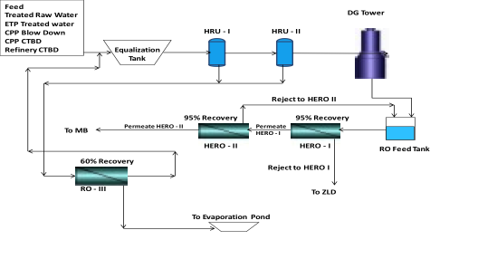
The various wastewater streams such as ETP treated water, CPP blow down, CPP CTBD, and refinery CTBD in various combinations are collected in the HRU feed tank. From here it is pumped to a set of HRU-I and HRU-II units followed by the degasser towers which is the pretreatment for the patented technology. The pretreated water is further treated in the first pass HERO-I and second pass HERO-II. First pass HERO-I block is an 1140 m³/hr system and second pass HERO-II block is an 1080 m³/hr system. Each pass is designed for 95% recovery. This ensures only 5% of incoming water finally goes to the ZLD plant. The internal high TDS effluents produced (32 m³/hr) are also separately treated in RO-III to recover another 60% of the water. The permeate of HERO-II is passed through mixed bed units which produces DM water, which meets the DM water needs of the entire refinery.
Design Water Analysis
| Sr. No. | Parameters | Feed | HERO II Permeate |
| 1 | Design Flow, m3/hr | 1020 | 865 |
| 2 | Total Suspended Solids, mg/l | 2 | NIL |
| 3 | Total Dissolved Solids, mg/l | 1609 | 5 |
| 4 | Oil & Grease, mg/l | 5 (Max) | NIL |
| 5 | BOD, mg/l | 5 (Max) | NIL |
| 6 | COD, mg/l | 20 (Max) | BDL |
| 7 | M Alkalinity as CaCO3, mg/l | 112 | 0 |
| 8 | Ca Hardness as CaCO3, mg/l | 240 | 0 |
| 9 | Mg Hardness as CaCO3, mg/l | 213.2 | 0 |
| 10 | Na + K as Na, mg/l | 365 | 0.84 |
| 11 | Chlorides as Cl mg/l | 549 | 0.74 |
| 12 | Total Silica as SiO2, mg/l | 47 | < 0.1 |
| 14 | pH | 6-8.5 | 8 – 10 |
Process Flow Diagram


